Problem Statement
During the geotechnical investigation for a hillside property in which the owners intended to build a custom home, the geotechnical engineer discovered a bowl-shaped dormant landslide on the site. This discovery, in combination with the close proximity to the San Andreas fault, meant that the hillside was poised to overtake any structure built on it—literally—if the earth were to shake with enough force. As such, a significant challenge was presented to the geotechnical and structural engineers: how to design a structure not only to resist earthquakes, but also an earthquake-induced landslide?
How ZFA Added Value
A Simple Concept with a Complex Solution
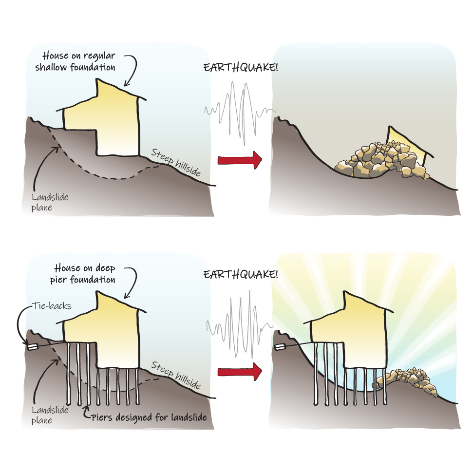
While many structures have been built on landslide-prone hillsides over time—knowingly or not—few have been designed to withstand the combination of forces that threaten the structure. However, the concept of resisting both an earthquake and simultaneous landslide is relatively simple: provide foundation elements that extend into sound soil beyond the landslide plane and that are designed to resist the forces of both an earthquake and landslide. While the best structural solutions often arise from straightforward concepts, the realization of this solution required extensive structural and geotechnical coordination, a thorough understanding of soil-structure interaction concepts, and intensive structural analysis.
The first step in designing a foundation to resist such large and unique loads was to work with the geotechnical engineer to understand the soil strength and stiffness properties. The geotechnical engineers provided geotechnical calculations and soil profiles that ZFA was able to analyze to determine soil spring properties, which are the values assigned to each square foot of soil to model how the soil reacts to loading from a structure. The results of the soil analysis were then input into a 3D full building analytical model that was subjected to lateral forces from three sources: the landslide, the soil during an earthquake, and the structure above during an earthquake.
In addition to the steel-encased concrete piers that were to penetrate through the landslide plane into competent soil, horizontal steel cable tiebacks were used in tandem to anchor into the stable hillside. Multiple variables affected the structural behavior of the foundation, including the slip plane geometry; pier spacing, depth, and diameter; and tieback layout and stiffness. The team iterated the design to vary pier and tieback size, spacing, and location to find the most efficient, cost-effective design that met the structural performance goals. To reduce the weight of soil contributing to the inertial forces on the foundation, Geofoam—high density, lightweight polystyrene—was used behind the retaining walls, which reduced the number and depth of the piers. The final design included 88 18-inch diameter piers and 20 tiebacks underneath the 5,100 square-foot home.
The Result
Using strong collaboration with the geotechnical team and the ability to pursue complex analysis to realize a straightforward concept, ZFA helped design a safe, stable structure on a site that would have otherwise been either unsafe or unbuildable.